Examples
The three data structures that Mugen provides to the user are the
scheme_graph, the logic_network, and the node. A scheme_graph
is used to represent a clocking scheme of some fixed size and with some fixed
connectivity. A logic_network is the result of synthesis and corresponds
to the physical mapping of a logic network on a clocking scheme. Each
node of the logic_network is placed on some grid cell and connected
to some adjacent nodes, primary inputs, or primary outputs.
In the first (rather trivial) example we use a scheme_graph to create a
clocking scheme on a 1x1 grid. Next, we disable the use of majority gates. We
then specify that we want to synthesize a single 2-input AND function.
Generally, specifying which functions to synthesize is done using a list of
binary lists in which each entry in the list corresponds to a function. Note
that the most significant bit of each function is the last entry in the list.
Finally, in this example we iterate over all logic_network objects that
satisfy the specification and print them to the standard output.
from graph import scheme_graph

g = scheme_graph(shape=(1,1))
g.enable_maj = False
functions = [[0,0,0,1]]
for net in g.synthesize(functions):
    print(net)
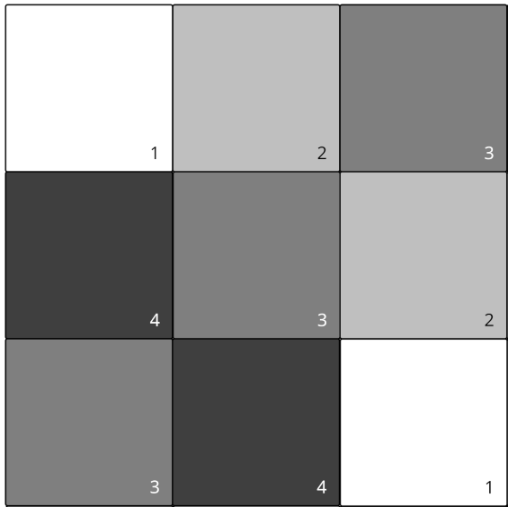
In the next example, we create a 3x3 USE clocking scheme. Again, we disable the majority gate, since it is not supported by the USE scheme. An important difference here is that we add a number of so-called virtual connections between different coordinates in the clocking scheme. These connections determine how information flows accross the clocking scheme, since they specify how tiles in the scheme may be connected to others. The key word here is may, since the tiles need not use all their possible virtual connections. They are simply used as a specification to the synthesis process. During synthesis some of them will be used to synthesize and place a logic network on the clocking scheme. Note that grid coordinates are accessed in a zero-indexed way. Coordinate (0, 0) corresponds to the top-left coordinate of the scheme. Coordinate (x, y) corresponds to the grid cell at horizontal position x and vertical position y.
To better understand the virtual connections we define here, see the figure below the code snippet. It is a picture of the 3x3 USE scheme. Note that tiles may fanout to other tiles with a clock number that is exactly one higher. Similarly, they may have fanin from other tiles with a clock number that is one lower (we wrap around to the highest number at zero). You can verify that the virtual connections we add using Mugen correspond to those defined by the clocking scheme.
from graph import scheme_graph

g = scheme_graph(shape=(3,3))
g.enable_maj = False
g.add_virtual_edge((0, 0), (1, 0))
g.add_virtual_edge((1, 0), (2, 0))
g.add_virtual_edge((1, 0), (1, 1))
g.add_virtual_edge((0, 1), (0, 0))
g.add_virtual_edge((1, 1), (0, 1))
g.add_virtual_edge((1, 1), (1, 2))
g.add_virtual_edge((2, 1), (2, 0))
g.add_virtual_edge((2, 1), (1, 1))
g.add_virtual_edge((0, 2), (0, 1))
g.add_virtual_edge((0, 2), (1, 2))
g.add_virtual_edge((1, 2), (2, 2))
g.add_virtual_edge((2, 2), (2, 1))
functions = [[0,0,0,1,0,1,1,1]]
for net in g.synthesize(functions):
    print(net)
For many more examples, see the test_suite.py file in the Mugen repository.